
End-effector and ankle force/torque feedback
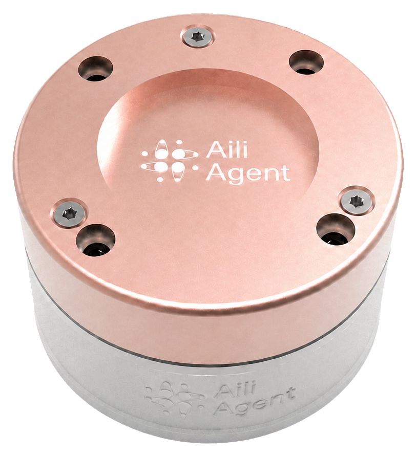
6dFT Motus™ Robot Joint 6-Axis Force Sensor
A core force-feedback component for embodied-intelligence, collaborative and industrial robots, built for fine control at the robot end-effector. It synchronously measures multi-axis forces and moments in the spatial Cartesian frame. Multiple selectable measurement ranges adapt to different task scenarios. Built-in intelligent algorithms keep inter-axis coupling, thermal drift and time drift low, so tuning and maintenance work stays minimal.
- Force / torque axes
- 6 DOF
- Sensor diameter
- Ø45–175 mm
- Model range
- 100–10000 N
- Official models
- 18
Dynamic Force / Torque Data Demonstration
Explore how six simulated channels can be organized for force and torque analysis. The values below are illustrative software-generated data, not readings from connected hardware.
- Fx
- 0.00 N
- Fy
- 0.00 N
- Fz
- 0.00 N
- Mx
- 0.00 Nm
- My
- 0.00 Nm
- Mz
- 0.00 Nm
This dashboard uses slowly changing simulated values. No physical sensor is connected.
Core Capabilities
The capability points below are taken from the official product material for this family.
Synchronous measurement of multi-axis forces and moments in the spatial Cartesian frame
Multiple selectable measurement ranges adapt to different task scenarios
Built-in intelligent algorithms for low inter-axis coupling and low thermal / time drift
Little tuning and maintenance work required
Quick Start
A practical integration sequence; final mechanical and electrical details follow the official technical file.
Select the model
Match the expected load to one of the official variants in this family.
Mount at the measurement point
Confirm the mechanical interface and protect the sensing body from unintended loads.
Connect data acquisition
Connect the specified power and communication interface according to the official technical file.
Zero, verify and acquire
Zero the unloaded sensor, verify channel directions, then use the measured data in the control workflow.
Technical Specifications
| Parameter | Specification |
|---|---|
| Sensor material | Stainless-steel body + aluminium-alloy housing |
| Sensor type | Resistive strain-gauge |
| Fz range (N) | 500~4000 |
| Fxy range (N) | 250~2000 |
| Mz range (Nm) | 20~120 |
| Mxy range (Nm) | 8~60 |
| Overload rating (%) | 150~1200 |
| Non-linearity (%F.S) | <0.1~<0.5 |
| Repeatability (%F.S) | <0.1~<0.5 |
| Thermal drift (%F.S) | <0.2~<1.6 |
| Zero drift (%F.S) | <0.1~<0.8 |
| Signal-acquisition board | Built into the sensor body |
| Communication interface | TypeC+4P serial port (customizable) |
| Power supply | DC5V 500mA |
| Digital resolution | 24-bit ADC |
| Sampling frequency | 100~2000Hz |
| Filtering | IIR 1000Hz low-pass + 50Hz mains-frequency notch |
| Built-in algorithms | Decoupling, zeroing, compensation, data fusion, self-diagnosis |
Application Scenarios
Current product content and selection relationships support the following customer tasks.
For wrist, ankle and robot-arm end-effector control tasks.
- APPLICATION 01
Embodied-intelligence robots
End-effector and ankle force/torque feedback - APPLICATION 02
Collaborative robots
End-effector and ankle force/torque feedback - APPLICATION 03
Industrial robots
End-effector and ankle force/torque feedback - APPLICATION 04
End-effector fine control
End-effector and ankle force/torque feedback
Applicable Robots and Mounting Locations
Robot types and locations below are generated from the current selection relationships rather than page-specific marketing copy.
Current selection: Humanoid Robots · End-effector and ankle force/torque feedback
- Humanoid Robots
- Collaborative Robots
- Industrial Robots
- Wrist
- Arm end effector
- Ankle
Select a model
- M6F-D045-250
- Axes
- 6
- Diameter
- 45
- Range
- 150
- M6F-D045-500
- Axes
- 6
- Diameter
- 45
- Range
- 300
- M6F-D055-100
- Axes
- 6
- Diameter
- 55
- Range
- 100
- M6F-D055-200
- Axes
- 6
- Diameter
- 55
- Range
- 200
- M6F-D055-600
- Axes
- 6
- Diameter
- 55
- Range
- 600
- M6F-D075-200
- Axes
- 6
- Diameter
- 75
- Range
- 200
- M6F-D075-700
- Axes
- 6
- Diameter
- 75
- Range
- 700
- M6F-D075-1K
- Axes
- 6
- Diameter
- 75
- Range
- 1000
- M6F-D075-3K
- Axes
- 6
- Diameter
- 75
- Range
- 3000
- M6F-D095-800
- Axes
- 6
- Diameter
- 95
- Range
- 800
- M6F-D095-2K
- Axes
- 6
- Diameter
- 95
- Range
- 2000
- M6F-D115-1K
- Axes
- 6
- Diameter
- 115
- Range
- 1000
- M6F-D115-2K
- Axes
- 6
- Diameter
- 115
- Range
- 2000
- M6F-D135-2.5K
- Axes
- 6
- Diameter
- 135
- Range
- 2500
- M6F-D135-4K
- Axes
- 6
- Diameter
- 135
- Range
- 4000
- M6F-D175-1K
- Axes
- 6
- Diameter
- 175
- Range
- 1000
- M6F-D175-3K
- Axes
- 6
- Diameter
- 175
- Range
- 3000
- M6F-D175-10K
- Axes
- 6
- Diameter
- 175
- Range
- 10000
Selected: M6F-D045-250
Downloads
- M6F-D045 · Whitepaper (PDF, ZH)Download PDF
Data note
Some parameter information continues to be verified. Refer to the official technical documentation.
Ready to Sense Force?
Give every wrist, ankle and end-effector an exact sense of the force it meets.